Stainless Steel Mirror Honeycomb Ceiling Suspended Bracket System: Technical Installation & Engineering Guide
Table of Contents
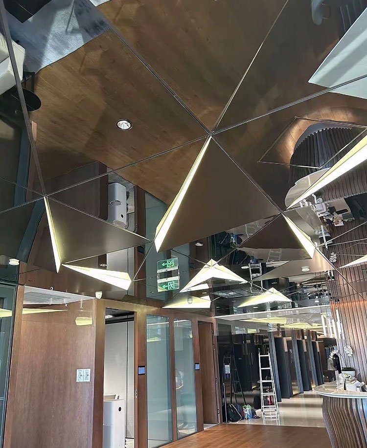
In modern high-end architecture, stainless steel mirror honeycomb ceilings are the top choice for commercial complexes, luxury hotel lobbies, and airport terminals. They deliver a brilliant mirror finish and a flatness that’s hard to match. But that flawless look only holds up when the suspension system behind it is done right. This article breaks down the angle-bracket suspension / side-mounted fixing keel system in full: what materials it’s made of, how it carries the load, and the standard installation process.
Structural and Material Composition of Stainless Steel Mirror Honeycomb Ceiling
A stainless steel mirror honeycomb ceiling panel isn’t a single sheet of metal. It’s a strong three-layer sandwich structure, where each layer is bonded together under high temperature and pressure with a polymer adhesive.
Face Sheet (Top Layer)
We use finely polished 8K mirror stainless steel in 304 or 316 grades, with a standard thickness ranging from 0.7mm to 1.2mm. To match different design styles, we can add colored finishes via PVD coating, including rose gold, champagne gold and black titanium. Custom textured surfaces like water ripple embossing are also available.
Honeycomb Core (Middle Layer)
The core adopts aluminum honeycomb with standard hexagonal cells. This natural structural design greatly boosts the panel’s rigidity, making it resistant to bending and compression. Meanwhile, it keeps the overall panel lightweight effectively.
Back Sheet (Bottom Layer)
Galvanized steel or aluminum sheets are used as the back base. It fully covers and protects the honeycomb core, stabilizes the internal stress of the whole panel, and provides reliable protection against moisture and corrosion.
Adhesive Layer
We apply high-performance two-part polyurethane adhesive or professional hot-melt adhesive film for lamination. This bonding material delivers excellent peel strength, firmly integrating the face sheet, honeycomb core and back sheet as a whole. It ensures no delamination or peeling even after long-term service.
Key Performance Advantages of Stainless Steel Mirror Honeycomb Ceiling
Compared with traditional stainless steel panels or ordinary metal ceilings, the stainless steel mirror honeycomb ceiling brings several performance advantages that are hard to beat:
Perfect Flatness, No Wavy Reflections
Thin mirror stainless steel is prone to “water ripple” or “funhouse mirror” distortion over large areas, because internal stress builds up in the sheet. The honeycomb core’s fine grid of cells supports the panel from underneath, eliminating local sagging and stress concentration, so the surface stays flat and the reflection stays clean.
Light Weight, High Stiffness
Working on the same principle as a honeycomb I-beam, the panel weighs 60–80% less than a solid stainless steel sheet of the same thickness. That cuts the load on the ceiling suspension system significantly, while still giving excellent resistance to wind pressure and impact.
Large Custom Sizes
Single panels can be made up to 1500 x 4000 mm or larger, depending on the design. Fewer panels mean fewer joints, which creates a continuous mirror surface and makes the space feel longer.
Excellent Fire and Sound Performance
The composite structure meets the A2 fire rating for building materials. The closed air cells inside the honeycomb also give good sound insulation, and help absorb vibration and cut noise.
Angle Bracket Suspended Keel Installation System and Bill of Materials
| Material Name | Specifications / Material | Function and Installation Location |
|---|---|---|
| Mirror-finish stainless steel honeycomb panel | 8K mirror-finish stainless steel + aluminum honeycomb core + backing sheet | Decorative surface layer; provides a flat, highly reflective visual effect |
| Expansion bolt | M8 / M10 carbon steel or stainless steel expansion bolt | Anchored to the overhead concrete structure; bears the tensile load of the entire system |
| Fully threaded rod | Ø8mm or Ø10mm galvanized threaded rod | Load-bearing suspension rod; allows for fine-tuning of elevation/height |
| Nut and washer | Matching nuts/lock washers for threaded rod | Double-nut locking (top and bottom) ensures a secure connection between the rod and the hanger |
| Ceiling grid hanger | 40mm or 60mm specialized load-bearing hanger | Connects to the lower end of the threaded rod; clamps and locks the main runner |
| Main runner (main keel) | 40mm×40mm or 60mm×60mm steel/aluminum runner | Serves as the horizontal, primary load-bearing framework for the ceiling system |
| L-shaped bracket | Galvanized steel or stainless steel L-bracket | Pre-fixed to the honeycomb panel backing/flange; acts as the panel mounting fixture |
| Fastening bolts/rivets | Self-tapping screws, blind rivets, bolt assemblies | Secures the bracket to the panel backing and locks the bracket to the side of the main runner |
Structural Mechanics and Connection Logic of the Installation System
The core idea of this installation method is structural separation and rigid fixing. From top to bottom, the load follows a clear path:
Supporting structure takes the weight → threaded rods hang it → hanger clips lock it in place → main keel carries it → angle brackets fix the panel from the side → honeycomb panel
All parts join into one connected assembly
Expansion bolts, screws, threaded rods, and hangers. At the top, an expansion bolt mates with a fully threaded rod (8mm or 10mm). The rod’s lower end passes through a hanger for 40mm or 60mm ceiling keels, and two nuts (one above, one below) fine-tune the height and lock it tight. The result is a rigid vertical hanger.
The hanger locks onto the main keel
The slot at the bottom of the hanger is designed to snap precisely onto a 40mm or 60mm main keel, so the keel won’t shift or twist in the horizontal plane.
The angle brackets are fixed to the panel back first
L-shaped brackets are pre-fixed to the back or the folded edge of the stainless steel mirror honeycomb panel with blind rivets or high-strength screws.
The angle brackets are then fixed to the keel
Once the panel is lifted into position, the L brackets already on the back sheet are screwed directly to the side of the main keel with self-tapping screws or machine screws. That levels the mirror panel precisely and holds it firmly in place.
Standard Installation Process and Key Steps
01
Layout, marking, and drilling
Mark control lines using a laser level and mark keel layout axes on the ceiling. Drill holes to fit expansion bolts securely.
→
02
Assemble the suspension unit
Screw fully threaded rods into expansion bolts with nuts, washers, and ceiling hangers to form a solid suspension assembly.
→
03
Snap in keels & fine-tune
Clip main keels into hangers and turn nuts to adjust the keel grid level within ±1.5mm for optimal reflection quality.
→
04
Pre-fit L brackets on panels
Lay panels face down and fix L-shaped brackets to the back and folded edges using rivets or screws according to keel spacing.
→
05
Lift panels & fix to keels
Lift panels to ceiling height and screw brackets into keels. Use elongated slots to fine-tune joints and flatness between panels.
Step 1: Layout, marking, and drilling.
Follow the design drawings. Use a laser level to mark the ceiling height control lines on the walls and columns, and mark the main keel layout axes and hanger rod positions on the ceiling slab. Drill the holes deep enough to match the expansion bolts, so the bolts get enough pull-out resistance once they’re in.
Step 2: Assemble the suspension unit (expansion bolt + threaded rod + hanger).
Screw an 8mm or 10mm fully threaded rod into the lower end of the expansion bolt, add the adjustment nuts and washers, and fit a 40mm or 60mm ceiling keel hanger. The bolt, nuts, rod, and hanger now form one solid suspension unit.
Step 3: Snap in the main keels and fine-tune the level.
Clip the 40mm or 60mm main keels into the hanger slots in parallel, then raise or lower the keels by turning the nuts on the threaded rods until the whole keel grid is level within ±1.5mm. How flat the keel grid is at this stage decides the mirror reflection quality at the end.
Step 4: Pre-fit the L brackets on the panel backs (prefabricate on the floor).
Lay each mirror honeycomb panel face down in the floor prep area so the mirror surface doesn’t get scratched. Following the designed keel spacing, fix the L-shaped brackets firmly to the back sheet and the folded edges around the panel with rivets or screws. Make sure the number and spacing of the brackets meet the wind pressure and fall-prevention requirements.
Step 5: Lift the panels and fix the brackets to the keels.
Use suction cups or a lifting frame to raise each panel, brackets already fitted, up to the ceiling height. Press the brackets against the side of the main keel and screw them on with high-strength screws. The elongated adjustment slots on the brackets let you fine-tune the joints and flatness between neighboring panels.
Technical Advantages and Construction Notes for the Angle Bracket Keel Installation System
Compared with the traditional hook‑on mounting method, this solution — where angle brackets are fastened to the panel back with screws or rivets and then secured to the keel — offers distinct practical benefits for construction projects:
High stability for large size panels
The rigid connection created by screws and angle brackets stops panels from loosening or shifting under indoor air pressure or vibration.
Individual panel removal
Every single panel can be repaired or replaced separately by removing the bracket screws, which greatly cuts long‑term maintenance costs.
No optical distortion on mirror surfaces
The high rigidity of honeycomb panels, together with multi‑point fixing via angle brackets, effectively prevents the optical distortion commonly seen with mirror‑finish stainless steel.
Key Construction Quality Guidelines
- When fastening angle brackets with rivets or screws, never drill all the way through the front mirror surface of the honeycomb panel.
- Select threaded rod diameters (8 mm / 10 mm) based on careful calculations of ceiling drop height and panel dead‑load weight.
- All metal parts, such as keels and angle brackets, should be galvanized for corrosion protection or made of aluminum alloy. This avoids galvanic corrosion caused by contact between dissimilar metals.
With reliable product quality and professional on‑site technical support, JYF METAL delivers complete stainless‑steel mirror honeycomb ceiling solutions for engineering clients worldwide.
Conclusion
Thanks to its three‑layer composite build and supporting honeycomb core, stainless‑steel mirror honeycomb ceilings solve the common problem of distortion for large‑area mirror stainless steel surfaces.
The suspension system made up of expansion bolts, threaded rods, hangers, main keels and L‑shaped angle brackets delivers clear load transfer, easy on‑site adjustment and excellent overall flatness.
Understanding these material properties and standard installation procedures is essential for building high‑quality mirror‑metal ceiling spaces.
For more details about stainless steel products, get in touch with JYF METAL.